by Ahmad Abdelkarim, DDS, MS, and Dipak Chudasama, BDS, MSc, MORTH RCS, MBA
What orthodontists should be looking for in cone beam CT scans
 |
 |
| Ahmad Abdelkarim, DDS, MS | Dipak Chudasama, BDS, MSC, MORTH RCS, MBA |
Cone beam computed tomography (CBCT) is now the imaging modality of choice for many radiographic studies in the field of dentistry. It is on the threshold of the orthodontic specialty as a mainstream diagnostic modality, and its applications in orthodontics have been recognized.1-3
CBCT can produce a complete initial record as a digital data set for all orthodontic patients. It is capable of imaging hard tissue of the dental and maxillofacial region, and it produces images with isotropic submillimeter spatial resolution. CBCT has allowed an improved visualization of anatomy and pathology when compared to other diagnostic modalities in dentistry.
Some concerns have been raised by dentists regarding CBCT radiation dosage. Although several studies4-6 report that this dose is much smaller than traditional CT imaging methods, the controversy regarding increased radiation from CBCT and appropriate radiological guidelines is a pertinent issue that needs to be addressed by the profession. While we do not recommend using CBCT on every orthodontic patient, it seems that the diagnostic benefits that can be obtained from CBCT are substantial.
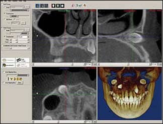 |
| Figure 1: An example of a popular layout of CBCT radiographs in Dolphin software. The three views are labeled in three different colors on top of each view. Also, the colors of the line differs according to the view—this should simplify the process for beginners. Note how the permanent maxillary right canine is visualized in 3D. The tooth is fully formed and impacted in a horizontal position. Follicle size is within normal limits. The root is close to the nasal fossa without any penetration. |
In most orthodontic cases, basic imaging such as panoramic, cephalometric, and periapical radiographs are sufficient adjunctive tools for diagnosis and/or confirmation of the clinical situation. On the other hand, there are reasons to use CBCT as an adjunct to imaging in orthodontic practice.7
To interpret CBCT images, one must examine the images in three dimensions: axial, coronal, and sagittal. 3D interpretations can be a challenging task. Most dental students do not get enough training in CBCT; therefore, most dentists are not comfortable interpreting those images. It should be emphasized that orthodontists, like all other clinicians, are responsible to report any occult pathology that might be encountered in the scan. Therefore, if an orthodontist is not qualified to read the scan, a referral to a radiologist should be considered.
However, orthodontists who use this imaging modality should begin to familiarize themselves with CBCT images. There are some patterns and findings that occur more than others. The objective of this article is to familiarize orthodontists with what they should be looking for in a CBCT scan.
How to Look
CBCT interpretation requires data to be processed using computer software to provide multiplanar reformatted (MPR) images and 3D visual representations (such as maximum intensity projection, surface, and volume rendering). The layout of CBCT radiographs is usually presented on the computer screen where axial, coronal, and sagittal views can be studied. An example of a popular layout in Dolphin Imaging version 10 software is presented in Figure 1. Changing one view requires moving the line on one of the other views. Each view should have two lines. Moving one of those lines renders changing one of the other views. The process is intuitive and user-friendly in any software.
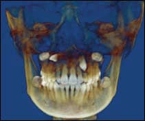 |
| Figure 2: An example of volume rendering of the same case in which the upper right canine was impacted in horizontal position and the left canine was vertically impacted. Both canines were in palatal position. Both upper primary canines were retained. |
Volume rendering seems to be a popular tool widely used among orthodontists, especially for impacted canines. An example is presented in Figure 2. The volume rendering view is merely a picture that is presented on a 2D object (a computer screen), and is not satisfactory for scan interpretation. It can be compared to architectural rendering illustrations that provide an appealing view of the building from the outside but not the inside. Therefore, it is imperative to always go through the whole volume to avoid any false negatives associated with the volume rendering view. Going through axial slices first from the most inferior to the most superior slice is recommended. After that, the coronal and sagittal views can be viewed and interpreted.
What to Look For
Typically, orthodontists should be looking for the following patterns and findings:
- Impacted teeth: Impacted tooth evaluation is the most widely used application of CBCT in orthodontics. 3D volumetric imaging can show the following: presence or absence of the tooth, size of the follicle, inclination of the long axis of the tooth, relative buccal and palatal positions, amount of bone covering the tooth, 3D proximity and resorption of roots of adjacent teeth, condition of adjacent teeth, local anatomic considerations, and the overall stage of dental development.8 CBCT overcomes limitations of basic imaging such as distortion, magnification, overlapping, and ghost images. Measurements can be performed. Figure 2 is an example of impacted maxillary canines.
- Temporomandibular joint evaluation: Although panoramic radiographs have been used to asses the TMJ, inherent anatomic diversity of the TMJ articulation, compounded by factors that influence 2D image presentation (such as anatomic superimposition, beam-projection angle, and patient positional changes) cast doubt on the validity of these reports.9 With CBCT, the TMJ can be clearly visualized in 3D.
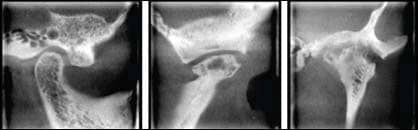 |
| Figure 3: Examples of CBCT radiographs of (above left) a normal TMJ, (above middle) Ely’s cyst, and (above right) severe degenerative joint disease. ABOVE LEFT) a sagittal view of a normal right TMJ condylar head. It is outlined by a uniform outline with no interruption. The posterior joint space is slightly reduced. ABOVE MIDDLE) Ely’s cyst is a pseudocyst and is a rare finding. Note the flattening of the condylar head. ABOVE RIGHT) A coronal view of the left TMJ shows severe DJD with lacunae formation, erosion of the medial and lateral slopes of the condylar head and mandibular fossa, and resorption of the lateral pole of the condylar head. |
Orthodontists should familiarize themselves with the normal appearance of the condyle head, mandibular fossa, and articular eminence. Any deviation from the normal should be reported, especially before orthodontic treatment is initiated. CBCT radiographic findings that may be encountered include interruption of the cortical bone of the condylar head, bifid condyle, flattening and/or remodeling of the condylar head, bifid condyle, osteophyte formation, lacunae formation, resorption and interruption of the articular eminence and/or mandibular fossa, erosion of anterior and/or posterior slopes of the condyle, and Ely’s cyst formation. The articular disk cannot be visualized in CBCT imaging. Figure 3 shows some examples of normal and abnormal TMJs.
- Paranasal sinus evaluation: Paranasal sinuses, including maxillary sinuses, frontal sinuses, sphenoid sinuses, and ethmoidal air cells, can be clearly visualized by CBCT. Some or all of the paranasal sinuses can be included in the CBCT scan volume, depending on its size. The orthodontist should be familiar with the appearance of a normal sinus. Mucositis, sinusitis, mucous retention cysts, polyps, antrolith, and mucocele are some intrinsic diseases that can be encountered. Neoplasms such as papilloma, osteoma, and squamous cell carcinoma can be encountered as well. Extrinsic diseases involving paranasal sinuses include inflammatory diseases such as periostitis. Benign odontogenic cysts are tumors that can be seen.10
 |
 |
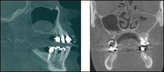
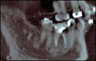
| Figure 4: ABOVE LEFT – Sagittal view of the right maxillary sinus shows an example of a mucous retention cyst. This common finding appears as a dome-shaped soft-tissue density and does not require further investigation or treatment. ABOVE RIGHT – A coronal view of a 23-year-old patient. Bony destruction should alert the clinician to also consider less common diseases, such as sinonasal tumors. Note the obliterated osteomeatal complex and infundibulum. Referral to ENT is recommended in this case. | Figure 5: The high-density areas seen in the carotid regions are consistent with calcifications of the carotid arteries. Referring this patient for a cardiology consult is beneficial. |
Mucous retention cyst is a common finding and does not require treatment. Also, a mild mucosal thickening is a common finding and does not require treatment if the patient is asymptomatic. Other findings require further investigation if encountered, and a referral to a physician or ENT specialist is recommended. Figure 4 shows two examples: one of them requires no further investigation, while the other requires alerting the patient of an active disease.
- Systemic findings: Even if a typical, young orthodontic patients seems to be generally healthy, orthodontists should make every attempt to examine the entire volume and rule out systemic findings. Although the chance of manifestation of a systemic disease on a maxillofacial CBCT volume is slim, the orthodontist should be careful not to miss it when it appears. Any clinician can be involved in a serious lawsuit if a significant finding has been missed. Nothing should be overlooked. For example, while medial arterial calcinosis (MAC) is considered to be an incidental finding by some clinicians, it can be associated with a serious problem such as an undiagnosed diabetic patient. In general, a wise clinician should look for cysts, tumors, trauma, and inflammatory changes on any radiographs. Figure 5 shows an example of calcifications in the carotid region that can be seen in CBCT images. On the other hand, some radiologists consider small calcifications that appear frequently on many radiographic studies as incidental findings that do not require further examination.
- Dental findings: Fortunately, dental findings encountered on CBCT images do not look significantly different from those found using periapical and panoramic radiographs. Interestingly, CBCT usually portrays the findings in a clearer way. Sometimes CBCT can reveal findings that cannot be visualized on periapical or panoramic radiographs. An example is presented in Figure 6. Therefore, orthodontists should familiarize themselves with the appearance of normal and pathologic findings on CBCT scans. Figure 7 shows an example of condensing osteitis, an inflammatory condition that requires treatment and referral to an endodontist or surgeon. Figure 8 presents an example of mesiodens.
- Orthognathic surgery: Patients are often curious about the exact treatment effects of orthognathic surgery. CBCT provides accurate analysis of preoperative and postoperative results.11 Superimposition of 3D CBCT models can help assess the craniofacial structures of patients undergoing orthognathic surgery.12,13 Preoperative and postoperative TMJ evaluation can be a further advantage of having both scans. Condylar resorption occurs in 5% to 10% of patients who undergo orthognathic surgery. Much of the condylar rotation resulting in remodeling is a direct result of the surgical procedures alone.14 Software applications for airway analyses following CBCT volumetric data are also available.
- Vertebral body evaluation: Cervical vertebral maturation is significantly related to skeletal maturation and can be used to predict skeletal age, a useful input in determining growth potential for planning orthodontic treatment. 2D sagittal views provide a good reference to observe the shape changes of cervical vertebrae in various growing periods; however, CBCT adds a potentially useful third dimension. Segmentation of individual vertebrae is possible from CBCT volumetric data sets. This provides a 3D approach to the biologic aging of orthodontic patients by using images of the cervical spine. It also has potential to help the study of disease processes such as spinal fractures consequent to osteoporosis.15
 |
 |
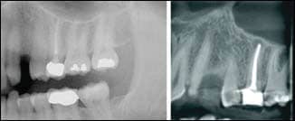
| Figure 6: An example of a cropped panoramic radiograph (A) versus a sagittal view of CBCT (B). The periapical lesion on the maxillary left second molar is well visualized on the CBCT image but would have been missed on the panoramic radiograph. | Figure 7: A periapical low-density area observed around the roots of tooth #30 with reactive dense bone surrounding the low densities. Diagnosis was periapical pathology of pulpal origin with surrounding condensing osteitis. Unlike idiopathic osteosclerosis, enostosis, or exostosis, condensing osteitis is an inflammatory condition that requires treatment. |
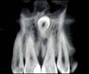 |
| Figure 8: A coronal view of CBCT presenting mesiodens where the crown is close to the nasal cavity. |
Conclusion
The use of CBCT in orthodontics is increasing. The improved diagnostic information that a CBCT renders is only justifiable if conventional methods are not adequate and an appropriate risk to benefit analysis is done, but considerable research has confirmed its accuracy and numerous applications in orthodontics. A prudent orthodontist should familiarize himself or herself with normal appearances versus the appearances of pathology to maximize patients’ health care and the orthodontist’s risk management.
Ahmad Abdelkarim, DDS, MS, is an orthodontic resident at Jacksonville University School of Orthodontics and a board-certified oral and maxillofacial radiologist. He can be reached at
Dipak Chudasama, BDS, MSC, MORTH RCS, MBA, is an assistant professor and director of research at Jacksonville University, School of Orthodontics. He can be reached at
References
- Mah JD, Hatcher D. Current status and future needs in craniofacial imaging. Orthod Craniofac Res. 2003;6(Suppl. 1):10-6.
- Vannier MW. Craniofacial computed tomography scanning: technology, applications and future trends. Orthod Craniofac Res. 2003;6(Suppl 1):23-30.
- Danforth RA, Dus I, Mah J. 3D volume imaging for dentistry: a new dimension. J Calif Dent Assoc. 2003;31:817-823.
- Siwerdsen JH, Jaffray DA. Cone-beam computed tomography with a flat-panel imager. Med Phys. 1999;26:2635–2647.
- Hashimoto K, Arai Y, Iwai K, Araki M, Kawashima S, Terakado M. A comparison of a new limited cone beam computed tomography machine for dental use with a multidetector row helical CT machine. Oral Surg Oral Med Oral Path Oral Radio Endo. 2003;95:371-377.
- Schulze D, Heiland M, Thurmann H, Adam G. Radiation exposure during midfacial imaging using 4- and 16-slice computed tomography, cone beam computed tomography systems and conventional radiography. Dentomaxillofacial Radiology. 2004;33:83-86.
- Danforth RA, Miles DA. Cone beam volume imaging: 3D applications for dentistry. Ir Dent. 2007;10(9):14-18.
- Walker L, Enciso R, Mah J. Three-dimensional localization of maxillary canines with cone-beam computed tomography. Am J Orthod Dentofacial Orthop. 2005;128(4):418-423.
- Hilgers M, Scarfe W, Scheetz J, Farman A. Accuracy of linear TMJ measurements with cone beam computed tomography and digital cephalometric radiography. Am J Orthod Dentofacial Orthop. 2005;128:803-11.
- White SC, Pharoah MJ. Oral Radiology, Principles and Interpretation. 6th Edition. St. Louis: Elsevier; 2009.
- Kau CH, Cronin A, Durning P, Zhurov AI, Sandham A, Richmond S. A new method for the 3D measurement of postoperative swelling following orthognathic surgery. Orthod Craniofac Res. 2006;9(1):31-37.
- Cevidanes LH. Styner MA. Proffit WR. Image analysis and superimposition of 3-dimensional cone-beam computed tomography models. Am J Orthod Dentofacial Orthop. 2006;129(5):611-618.
- Cevidanes LH, Bailey LJ, Tucker GR Jr, et al. Superimposition of 3D cone-beam CT models of orthognathic surgery patients. Dentomaxillofacial Radiology. 2005;34(6):369-375.
- Bailey LJ, Cevidanes LH, Profitt WR. Stability and predictability of orthognathic surgery. Am J Orthod Dentofacial Orthop. 2004;126 (3):273-277.
- Shi H, Scarfe WC, Farman AG. Three-dimensional reconstruction of individual cervical vertebrae from cone-beam computed-tomography images. Am J Orthod Dentofacial Orthop. 2007;131(3):426-432.