If you are a frequent reader of Orthodontic Products, you already know that I treat approximately 75% of my patients with Invisalign® from Align Technology Inc. What you may not know is that I spend considerable time and effort customizing each and every ClinCheck® plan. Over the past 10 years, I have encountered certain clinical situations where, in my hands, the default optimized attachments don’t always get the job done. In these situations, I substitute attachments of my own design that give me more predictable results.
In this article, I descend from the mountain to bestow upon my readers Dr Glaser’s 10 commandments of attachment design. These 10 simple rules will help to keep your patient’s Invisalign treatment on track. Use them wisely!
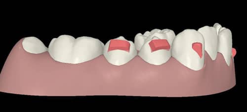
Figure 1: Here, 4 mm wide occlusally beveled rectangular retentive attachments on the lower 4’s and 5’s are used to support leveling of the lower Curve of Spee.
1. Thou shalt use 4 mm wide occlusally beveled rectangular retentive attachments on the lower 4’s and 5’s to support leveling of the lower Curve of Spee.
Aligners require posterior retention to effectively intrude the lower incisors to level the Curve of Spee. Why? Think Newton’s Third Law. The “action” force comes from the anterior portion of the aligner pressing down on the lower anterior teeth. The “reaction” is for the distal portion of the aligner to pop off the posterior teeth. Your patient may note that the back of the aligners feels “bouncy.” Herein lies the problem. If the aligner is dislodged from the molars, the intrusion forces to the lower anteriors are diminished or lost completely. Clinically, the patient’s deep overbite will not correct.
This situation can be remedied by placing 4 mm wide occlusally beveled rectangular attachments on the lower 4’s and 5’s (Figure 1). These attachments provide “grip,” so that the aligners stay firmly on the posterior teeth, allowing for effective forces of intrusion. “What about unwanted posterior extrusion?” you ask. While it is true that the reaction force will tend to place extrusion forces against the attachments on the lower 4’s and 5’s, the forces of occlusion effectively block any unwanted posterior extrusion.
2. Thou shalt trash optimized rotation attachments on the lower 4’s and 5’s, and substitute the attachments described in Commandment #1 in situations where leveling the Curve of Spee takes priority over premolar rotation.
Another issue that can interfere with levelling of the lower Curve of Spee is software-related. Optimized rotation attachments are one of many SmartForce® features integrated into the ClinCheck software. All SmartForce features, optimized rotation attachments being one of them, have built-in protocols that place the attachments at certain clinical thresholds. Optimized rotation attachments are placed automatically on the premolars when rotations of 5° or greater are detected. But what happens when you need premolar anchorage to level the lower Curve of Spee? The smaller optimized rotation attachments are not retentive enough to support the intrusion of the lower incisors. When this situation arises, I use 3D controls in ClinCheck Pro to trash the optimized rotation attachments, and substitute the 4 mm wide occlusally beveled rectangular attachments described in Commandment #1. Typically, the larger attachments are more than adequate to gain the desired rotation. If, after the bite has been opened, there is still the need for additional rotation of the premolars, I will allow the placement of optimized rotation attachments during refinement.
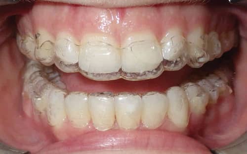
Figure 2: A side effect of adding palatal root torque is slippage of the aligner off the anterior teeth.
3. Thou shalt use 3 mm wide gingivally beveled rectangular attachments when applying palatal root torque U 2112.
Another SmartForce feature is power ridges. Power ridges are designed to place torque on upper and lower incisors. I have encountered a performance issue when there are four power ridges on the upper anterior teeth in situations where I want to add palatal root torque (PRT). A side effect of the torquing force tends to make the aligners slip off the anterior teeth, as depicted in Figure 2. When this situation arises, the aligners do not fully engage the anterior teeth and the torque will not express. Unfortunately, the software will not allow the placement of a retentive attachment on the same tooth as a power ridge. My solution for this problem is to prescribe the desired palatal root torque, but I ask my technician to delete the power ridges and add 3 mm wide gingivally beveled rectangular attachments to keep the aligners fully engaged on the teeth (Figure 3). I still get the torque, but don’t have to worry about the aligners disengaging from the teeth. Try it!
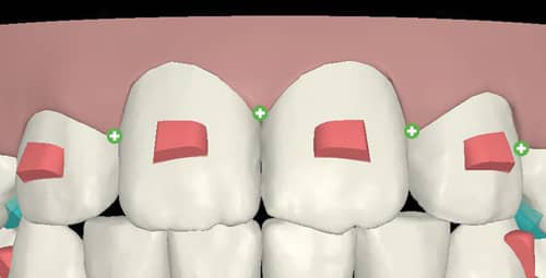
Figure 3: Retentive attachments on the upper incisors keep aligners engaged when adding palatal root torque.
4. Thou shalt not use power ridges, except for single tooth torquing.
Not only do I find the power ridge-related performance issue as described in Commandment #3, there’s another issue my patients have with power ridges: comfort. In general, I hear few complaints from patients regarding aligner comfort. However, power ridges, especially several in a row, can be a source of both lip irritation and speech issues. More frequently in adults than teens, patients who spend their days talking—teachers, for example—have complained about saliva bubbling out around the gingival gap created by the power ridge, as well as significant irritation to the mucosa of the lip. I have heard enough of these complaints to virtually eliminate power ridges from my repertoire, with one exception—applying root torque to a single tooth. Most often encountered in situations where a lower incisor root requires lingual root torque, I will allow placement of a power ridge. I will support this movement with a small rectangular attachment on the adjacent teeth to ensure that the aligner stays fully engaged and the torque expresses. While I still run the risk of causing irritation to the lip, one power ridge doesn’t seem to be as problematic. We also empower our patients to use an emery board to smooth the gingival aspect of the aligner if necessary.
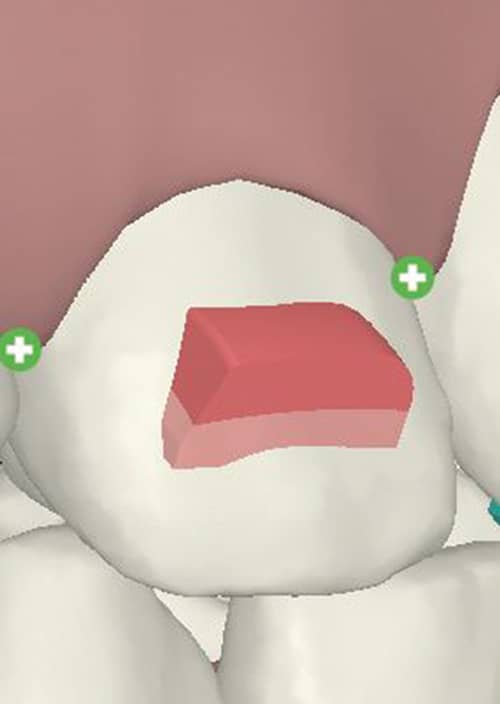
Figure 4: Attachment provides added “aligner grip” for absolute extrusion.
5. Thou shalt use 4 mm wide gingivally beveled rectangular attachments on the upper laterals to support absolute extrusion.
There are two ways to extrude a tooth: 1) relative extrusion and 2) absolute extrusion.
Relative extrusion occurs when a tooth is being tipped lingually. Think habit-induced anterior open bite. Eliminate the habit and the anterior teeth simultaneously retract and relatively extrude; and PRESTO! the bite closes down. Relative extrusion is an “Invisalign free ride.” You don’t need any special attachments or ClinCheck modifications to achieve relative extrusion, and it’s very predictable.
Absolute extrusion—physically grabbing a tooth and extruding it from the alveolus—can be quite challenging to achieve predictably with aligners, especially on pesky maxillary lateral incisors. This is probably the most common area to encounter non-tracking, and it’s not surprising. It has been said that with Invisalign, we are trying to move “slippery teeth with a wet piece of plastic.” In addition, the maxillary lateral incisors are small, with little surface area for the aligners to engage. This is a situation where 3D controls in ClinCheck Pro come in handy. In instances where absolute extrusion of the maxillary incisors is desired, I place a 4 mm wide gingivally beveled attachment to provide additional “aligner grip” (Figure 4). They work quite well, and they’re not as much an aesthetic problem as you would think. I use Flow Tain® from Reliance Orthodontic Products Inc as my attachment material. It’s very translucent and picks up the natural shade of the tooth. We explain to our patients that this attachment is absolutely necessary to achieve a good result, and I don’t negotiate! I would rather settle the issue of attachments with my patients at the beginning of treatment versus running the risk of the dreaded “I spent all this money and my tooth isn’t straight” conversation a year or more into treatment.
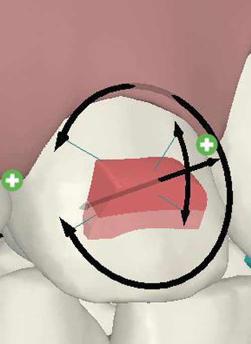
Figure 5: ClinCheck Pro 3D controls used to roll the bevel gingivally.
6. Thou shalt use 3D controls in ClinCheck Pro to rotate the bevels of these upper lateral attachments so the bevel blends smoothly into the gingival aspect of the tooth.
There is a debate amongst Invisalign educators as to the orientation of the bevel for optimal predictability of absolute extrusion of incisors. One school of thought contends that the bevel should be oriented towards the incisal edge, resulting in a large “ledge” at the gingival aspect of the attachment. This ledge, the thinking goes, provides maximum grip for the aligner and provides the best opportunity to gain absolute extrusion. This rationale makes sense, but there’s a problem. The interface between the ledge of the attachment and the aligner is not very forgiving if the tooth begins to get off track and goes into “failure mode.” If this occurs, even slightly, the aligner will not fit properly over the attachment and may even begin to exert an unwanted lingual force. Unwanted lingual forces are bad, and may lead to the opposite of the desired tooth movement, meaning intrusion rather than extrusion.
The opposing school of thought contends that the bevel should be oriented gingivally. While providing somewhat less grip, the long gingival bevel allows more forgiveness in failure mode. In other words, if the tooth begins to get off track, there is still plenty of engagement between the aligner surface and the bevel.
My personal preference is the latter, beveling the attachment towards the gingival, mimicking the orientation of optimized extrusion attachments, which have been biomechanically tested by Align Technology to be the best orientation for absolute extrusion. By manipulating these attachments using 3D controls, I roll the bevel gingivally and make the attachments 4 mm in length to make a broad flat surface to gain as much surface area as possible, and I find this to work well (Figure 5).
7. Thou shalt use the same attachment as above to support intrusion of the upper central incisors.
Have you ever encountered a situation where you want to intrude UR1 UL1? You set up your ClinCheck to achieve this movement, but clinically you notice that there is gapping (non-tracking) at the level of the maxillary lateral incisors. Your first instinct may be to consider a bootstrap elastic on the laterals to pull them back into the aligner, because it appears the laterals are not tracking. If we analyze this situation more closely, it’s not the laterals that are not tracking; it’s the centrals. Why? Imagine each aligner stage intruding the upper centrals .25 mm per tray. What happens if the centrals don’t intrude? The aligner, when seated, will first contact the incisal edges of the upper centrals, and will not allow full seating of the tray on the adjacent laterals. Clinically, this appears to be lateral non-tracking, but the real culprit is lack of intrusion of the centrals—it’s the centrals not tracking! To reduce the chances of this occurring, place the same attachment as described in Commandment #6, a 4 mm wide gingivally beveled rectangular attachment on the upper laterals to support the intrusion of the centrals. These attachments provide anchorage to keep the aligners engaged on the teeth and transmit the intrusion forces appropriately to the centrals.
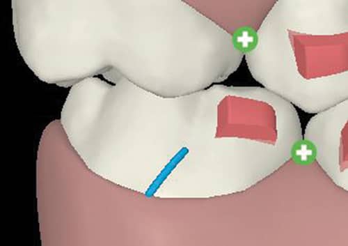
Figure 6: When using Class II elastics, an occlusally beveled rectangular attachment is placed on the mesial of the lower 6’s for aligner retention.
8. Thou shalt place a 3 mm wide occlusally beveled rectangular attachment on the mesial of the lower 6’s for aligner retention whilst using Class II elastics.
I treat a lot of teens with Invisalign. Naturally, many of these patients have Class II malocclusions. In a previous article in Orthodontic Products, I described in detail my Class II protocol. In my protocol, I prefer to use precision cut elastic hooks on the lower molars to retain the elastics. To prevent the aligners from dislodging posteriorly from the pull of the elastics, I add a 3 mm wide occlusally beveled rectangular attachment to the mesio-buccal aspect of the lower first molars to provide aligner retention (Figure 6). This works very well and eliminates the need to bond a button or bracket, which can fall off during treatment and cause an unwanted emergency appointment.
9. Thou shalt trash optimized attachments on the upper 3’s and place a standard attachment when a precision cut elastic hook is needed on the upper 3’s.
Similarly, I use precision cut elastic hooks on the upper 3’s to retain the Class II elastics. You may have encountered situations where your technician informs you that an optimized attachment cannot be placed on the same tooth as a precision cut. If this occurs, trash the optimized attachment and place a standard attachment that best approximates the shape and orientation of the optimized attachment. This way, you can have your elastic hook and an attachment on the same tooth.
Figure 7: In open bite cases, a 4 mm wide occlusally beveled rectangular attachment is placed on the upper 4’s and 5’s to support intrusion of the upper molars.
10. Thou shalt place 4 mm wide occlusally beveled rectangular attachments on the upper 4’s and 5’s to support intrusion of the upper molars in thy open bite cases.
Treating open bites with Invisalign can be incredibly gratifying, especially in cases where upper molar intrusion is desired. Once again, we need to look at Newton’s Third Law. In this case, the “action” force is intrusion of the upper molars. The “reaction” is the dislodgement of the aligner in the region of the upper premolars. If the aligner is allowed to dislodge on the premolars, the intrusion forces are diminished or lost completely to the molars and the open bite won’t close. To prevent this from happening, place 4 mm wide occlusally beveled rectangular attachments on the upper 4’s and 5’s to support the intrusion of the molars (Figure 7). Here’s one more tip—overtreat the intrusion of the molars to a 2 mm posterior open bite, as aligners can routinely underperform in this area. OP

Barry J. Glaser, DMD, received his doctorate in dental medicine from The University of Pennsylvania School of Dental Medicine and earned his Certificate of Advanced Graduate Studies in Orthodontics from Boston University. He served as associate director of orthodontics at Montefiore Medical Center in New York City from 1992 to 1995. He has been in private practice in Cortlandt Manor, NY, since 1994. Glaser was an early adopter of Invisalign Teen and has extensive experience treating teens and adults of all malocclusions with Invisalign.