
by Neal D. Kravitz, DMD, MS
A simplified insertion protocol for orthodontic temporary anchorage devices
 |
A temporary anchorage device (TAD) is a titanium-alloy miniscrew, ranging from 6 to 12 millimeters in length and 1.2 to 2 millimeters in diameter, that is fixed to bone temporarily to enhance orthodontic anchorage.1
As an adjunctive procedure, the use of TADs have allowed the orthodontist to overcome anchorage limitations and perform difficult tooth movements predictably and with minimal patient compliance. This article will provide a simplified insertion protocol for placement of orthodontic TADs.
Site Selection
TADs maintain relative anchorage via a combination of mechanical grip, fibrous connection, and partial osseointegration. The primary determinants of stationary anchorage success are cortical bone thickness, soft-tissue health, and adequate bone stock.2,3 Ideally, TADs should be inserted into a region with high bone density and thin keratinized tissue, with 4 to 5 mm of interradicular bone stock.
Cortical bone influences primary mechanical stability. Regions with a bone density in the category of D2 (850 to 1250 Hounsfield Units, or HU) or D3 (350 to 850 HU) bone, such as the dentoalveolus, palatal paramedian region, palatal slope (mesial to the second molar), and zygoma are ideal for TAD insertion. In the posterior dentoalveolus, the greatest amount of interradicular bone is located between the second premolar and first molar, approximately 5 to 11 mm from the alveolar crest.4
Thin, attached tissue is located in dentoalveolus incisal to the mucogingival junction or in the palatal paramedian region. In the paramedian region, the attached tissue has a uniform thickness of 1 mm with little submucosal fat. Rising up the palatal slope, the attached tissue thickens, as does the layer of submucosal fat reaching a combined soft tissue thickness of 3 to 5 mm.5
Approximately 1.5 to 2 mm of bone stock is recommended between the root and the body of the TAD. Under a heavy force load, a TAD will tip and extrude 0.5 mm toward the direction of the pull.6 As the body of the TAD approximates the root surface, stationary anchorage reduces significantly.3 In the buccal posterior regions where the mucogingival junction is shorter (often less than 5 mm), the clinician may choose to diverge roots or place the TAD in alveolar mucosa in favor of achieving adequate bone stock.
The Debate Over Compound Topical Anesthetics
Compound topical anesthetics are nonregulated, custom-made, strong topical formulations, often containing high concentrations of both amide (lidocaine and prilocaine) and ester (tetracaine) anesthetics.
 |
Figure 1: Notable features of the Dual-Top button-top orthodontic TAD include a button-top head, which provides a built-in low-profile healing abutment and allows for “snap-on” attachment of auxiliaries, a gingival collar to reduce soft-tissue overgrowth, a body with reverse-buttress threading to ensure maximum retention, and a grooved sharp tip for easy insertion and reduced risk of slippage. |
Popular compound topical anesthetics, such as TAC 20% Alternate (20% lidocaine, 4% tetracaine, 2% phenylephrine) and Profound PET (10% lidocaine, 10% prilocaine, 4% tetracaine, 2% phenylephrine) are widely used by orthodontists for soft-tissue laser surgery and placement of TADs.7,8 Significant concern exists, however, regarding the safety of these anesthetics.
The risks regarding use of compound topical anesthetics are the following:
- They are not-regulated by the Federal Food Drug and Cosmetic Act;
- the maximum recommended dosage is unknown;
- they have a low therapeutic index (a narrow difference between optimal dose and toxic dose);
- they may be improperly mixed, measured, or labeled;
- prolonged application may cause tissue sloughing; and
- they may contain high concentrations of ester anesthetics, which can lead to para-aminobenzoic acid (PABA) anaphylaxis.9
Although I have never experienced complications with the use of compound topical anesthetics, due to the lack of federal regulation, I now only infiltrate with 4% Septocaine (1:100,000 epinephrine), with a 30-gauge short needle.
Insertion Technique
When selecting a TAD system, you should consider various factors, including the quality of the hand-driver, the quality and versatility of the TAD and associated auxiliaries, affordability, and your relationship with the sales representative, among others. In my office, I use the Dual-Top System (from Rocky Mountain Orthodontics, Denver) with both the straight hand-driver and the lingual hand-driver (for palatal insertions). Site selection will determine the diameter and length of the TAD. I primarily order the button-top design with a 1.6-mm diameter. I use either 6-mm length in the paramedian region and the 8-mm length in the dentoalveolus or palatal slope (Figure 1).
Prior to insertion, you need to decide whether to use a radiographic stent. In my office, radiographic stents are only used in the anterior region, where interradicular placement of TADs can be particularly challenging because of the chairside vantage point and proximity of the roots to the facial cortical plate. In the posterior buccal region, roots are diverged if needed, and TADs are placed using only panoramic evaluation.
Proper angle of insertion is important for cortical anchorage, biomechanical control, and avoidance of root contact. In the posterior buccal region, the angle of insertion should be 30º to 45º to the occlusal plane, with the exception of posterior impaction cases or edentulous regions in which the angle of insertion should approximate 90º to the occlusal plane (parallel to the sinus floor). Angulations less than 45º increase cortical bone-implant contact10 and minimize the likelihood of root perforation, but may increase the risk of TAD slippage.11
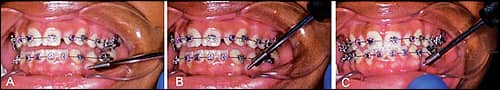 |
| Figures 2A-2C: Steepening the angle of insertion. (A) Engage bone with one to two turns of the hand-driver at an obtuse angle. (B) Steepen the angle of insertion to gain cortical grip. (C) Complete insertion at the desired angle of insertion. |
To avoid slipping along the periosteum, some clinicians make a purchase point in the cortical bone with a slow-speed. I do not own a slow-speed, nor do I advocate drilling the cortical plate. Rather, I begin insertion at an obtuse angle (45º), and turn the hand-driver once or twice, essentially creating a purchase point with the tip of the TAD. After cortical bone is gripped, I steepen the angle and complete insertion. With a quality TAD, the risk of tip breakage is unlikely (Figures 2A–2C).
 |
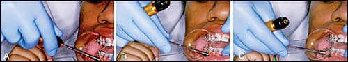
| Figures 3A-3C: Proper patient positioning. (A) Improper patient positioning prevents direct visualization. (B) Proper patient positioning allows direct visual access. The orthodontist is holding the near retractor. The patient is turned all the way sideways and holding the far retractor. (C) The V-shaped retractor helps to stabilize the hand-driver during insertion. The angle of insertion is 90º to the occlusal plane in the edentulous space. (The TAD in the photograph is a 1.6-mm diameter, 8.0-mm-long Dual-Top.) |
During placement, there is a tendency to inadvertently pull the hand-driver toward your body, changing the horizontal angle of insertion.11 For a TAD 8 mm long, every degree of variation from the ideal angle of insertion will cause the tip to deviate by 0.1 mm. So, for example, 10º of variation results in approximately 1 mm of deviation at the tip.12 To stabilize my hand-driver and gain direct visualization of the surgical site, I use two adult V-shaped photographic cheek retractors and instruct the patient to turn his or her head completely to the opposite side (Figures 3A–3C).
 |
| Figures 4A-4C: Wiggling the hand-driver from the TAD head after insertion. (A) Insertion at 45º complete. (B) Remove the handle of the hand-driver and gently wiggle the shaft. (C) The shaft of the hand-driver will wiggle away from the TAD head with minimal torsional stress. |
Once the TAD has been inserted, torsional stress from wiggling the hand-driver off the TAD head can weaken primary stability. When removing the hand-driver, I separate the hand-driver handle from its shaft and then gently remove the shaft from the miniscrew head (Figures 4A–4C).
 |
| Figures 5A-5C: Removal of a TAD from a transfer patient. (A) The patient presents with a TAD from a different system. (B) Grab the TAD with a mathieu plier, then lock the plier and twist. (C) Removal of a TAD without the hand-driver. |
Occasionally, a transfer patient will enter your office with TADs placed from a different kit. When I am ready to remove the TAD, I will clamp down on the head with a mathieu plier and twist. I often remove TADs without local anesthesia (Figures 5A–5C).
Postinsertion Protocol
After successful TAD insertion, I recommend that patients take OTC analgesics per discomfort for 1 to 2 days. For patients with poor oral hygiene, or for surgeries in the posterior mandible, I prescribe Chlorhexidine rinse to reduce the incidence of peri-implant aphthous ulceration and soft-tissue overgrowth. I ask all patients to return in 1 to 2 weeks for a surgical follow-up and loading of the TAD.
Patient Contraindications
TADs are contraindicated in heavy smokers, patients with bone metabolic disorders, or patients undergoing prolonged bisphosphonate medication. TADs are approved by the FDA for patients 12 years and older; however, adolescent patients who have not completed skeletal growth should not undergo TAD placement directly into the maxillary palatal midline suture.11
Conclusions
Regarding who should place TADs, renowned orthodontist and international educator Jay Bowman, DMD, MSD, writes, “We [Orthodontists] can do this and should do this ourselves.”13 Orthodontists placing their first TADs should consider taking a hands-on or in-office CE course and should treatment-plan for significant root divergence or palatal placement. When in doubt, remember it is always better to simplify your surgery and modify your mechanics.
Neal D. Kravitz, DMD, MS, is in private practice in South Riding, Va, and White Plains, Md. He is a Diplomate of the American Board of Orthodontics, and is on the faculty at the University of Maryland and Washington Hospital Center. He can be reached at or kravitzorthodontics.com.
References
- Kravitz ND, Kusnoto B, Tsay TP, Hohlt WF. The use of temporary anchorage devices for molar intrusion. J Am Dent Assoc. 2007;138:56-64.
- Miyawaki S, Koyama I, Inoue M, Mishima K, Sugahara T, Takano-Yamamoto T. Factors associated with the stability of titanium screws placed in the posterior region for orthodontic anchorage. Am J Orthod Dentofacial Orthop. 2003;124:373-378.
- Kuroda S, Yamada K, Deguchi T, Hashimoto T, Kyung HM, Takano-Yamamoto T. Root proximity is a major factor for screw failure in orthodontic anchorage. Am J Orthod Dentofacial Orthop. 2007;131:S68-73.
- Poggio PM, Incorvati C, Velo S, Carano A. “Safe zones”: a guide for miniscrew positioning in the maxillary and mandibular arch. Angle Orthod. 2006;76:191-197.
- Kim JH, Yun HS, Park HD, Kim DH, Park YC. Soft-tissue and cortical bone thickness at orthodontic implant sites. Am J Orthod Dentofacial Orthop. 2006;130:177-182.
- Liou EJ, Pai BC, Lin JC. Do miniscrews remain stationary under orthodontic forces? Am J Orthod Dentofacial Orthop. 2004;126:42-47.
- Kravitz ND, Kusnoto B. Placement of mini-implants with topical anesthetic. J Clin Orthod. 2006;40:602-604.
- Graham JW. Profound, needle-free anesthesia in orthodontics. J Clin Orthod. 2006;40:723-724.
- Kravitz ND. The use of compound topical anesthetics: a review. J Am Dent Assoc. 2007;138:1333-1339.
- Deguchi T, Nasu M, Murakami K, Yabuuchi T, Kamioka H, Takano-Yamamoto T. Quantitative evaluation of cortical bone thickness with computed tomographic scanning for orthodontic implants. Am J Orthod Dentofacial Orthop. 2006;129:721e7-12.
- Kravitz ND, Kusnoto B. Risks and complications of orthodontic miniscrews. Am J Orthod Dentofacial Orthop. 2007;131:S43-51.
- Estelita CB, Jason G, Chiqueto K, de Freitas MR, Henriques JF, Pinzan A. A three-dimensional radiographic-surgical guide for mini-implant placement. J Clin Orthod. 2006;40:548-554.
- Osterman WL. Who places miniscrews? J Clin Orthod. 2008;42:519-527.