by DAVID SARVER, DMD, MS
How to build, place, and remove a rapid palatal expander
 The indications for expansion of the maxilla are numerous, as are the number of appliances used for maxillary expansion. Orthodontists advocate both slow expansion and rapid palatal expansion, using Quad-helixes, thermally activated expansion devices, rapid expansion, or surgical expansion of the maxilla.
Indications for rapid palatal expansion include: 1) correcting of unilateral or bilateral crossbites, 2) increasing maxillary arch width to increase arch length, 3) increasing apical base width to facilitate improvement of posterior buccal root torque, 4) reducing buccal corridors, 5) mobilizing maxillary sutures to facilitate correction of Class III midfacial deficiency through maxillary protraction, and 6) reducing nasal resistance to normalize breathing patterns.
Orthodontists began using bonded rapid palatal expansion instead of banded appliances for three basic reasons. The first was to reduce the number of appointments required for fabrication and placement. Banded appliances require an appointment for separator placement, followed by a banding appointment with impressions, and then a third appointment for placement of the appliance. To fabricate and place a bonded appliance, an impression is all that is required for fabrication in the laboratory; the appliance can be placed at the next appointment. Second, the bonded appliance produces a reduction in posterior tooth tipping, a problem frequently experienced with banded rapid palatal expansion.1 Third, the bite-block effect facilitates correction of anterior crossbites.2
The Discriminating Choices in Rapid Palatal Expansion
The early studies on banded rapid palatal expansion3,4 reflected a downward and forward movement of the maxilla in response to rapid palatal expansion.
In a study of 20 consecutive cases,5 it was documented that the inferior and anterior displacement of the maxilla was lessened in the bonded appliance group with a slight superior movement of the posterior aspect of the palatal plane, negating the downward and backward rotation of the mandible seen with banded rapid palatal expansion. The anterior aspect of the maxilla also experienced a downward and posterior movement.
The great clinical significance of these findings is summarized as the following:
1) In patients with short faces or short-face Class III tendencies, we recommend the use of the banded rapid palatal expander to take advantage of the downward and forward movement of the maxilla.
2) In patients with long faces, Class II tendencies, or open-bite tendencies, we recommend the bonded rapid palatal expander since this not only negates, but also may possibly improve, the dental and skeletal relationships.
Building a Rapid Palatal Expander
 |
 |
 |
 |
Here are the six steps that I use in constructing a rapid palatal expander:
1) Cast preparation: The cast is marked with a pencil for undercuts, and these undercuts are then waxed out using a wax spatula. The purpose of waxing the undercuts is to reduce interferences in placing the appliance, since snapping the appliance into place would make it even more difficult to remove.
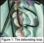
2) Fabrication of the debonding loop: The debonding loop is made of .036 wire, crosses the occlusal surfaces at the embrasure and touches the occlusal surface of the teeth, and is bent to rest in the mesial and distal fossae of the first molar (Figure 1, page 30). The loop is then secured with wax to actually touch the model in the fossae (the importance of this will be described later), but with 1 mm of clearance everywhere else. This provides room on the occlusal surface for the acrylic to flow underneath the wire, thus maintaining its incorporation into the appliance. The purpose of blocking out 1 mm from the buccal aspect model is to provide clearance so that when using the debonding loop upon removal, the beaks of the recommended Weingart pliers can be placed into position without causing the patient discomfort.
3) Fabrication of the wire framework: A .030 wire framework is bent to support the acrylic pad and to serve as a fulcrum point for the debonding loop (Figure 2). The wire framework travels through the mesial embrasure of the cuspid and the distal of the first molar, and actually touches the debonding loop on the facial surface.
4) Securing the framework to the expander: The expander is placed into a ball of rope wax, again with about 1–2 mm of clearance from the palate. Note that the arms of the expander are bent to touch the framework, and the framework is soldered to the arms.
5) Fabrication of the pad: In our office, the occlusal pad is fabricated with a sprinkle technique. Some offices use other approaches, but we prefer the sprinkle technique because once the acrylic is in a “doughy” state, auxiliaries such as headgear tubes, archwire tubes, and traction hooks may be placed.
6) Finishing the appliance: Once cured in a pressure pot, the appliance is trimmed for excess and sized to the height and contour previously marked on the model.
We then use the same bur to drill holes in the palatal cusp tips of the maxillary molars and premolars. The purpose of the occlusal holes is to allow extrusion of excess bonding material that, in turn, keeps material from extruding in the undercuts. It also reduces cleanup at the border of the appliance and adds to the mechanical retention of the appliance to the bonding composite.
The finished appliance offers clearance between the appliance and the gingival margin to help with cleaning (Figure 3).
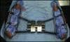
The occlusal holes also serve as a marker for the clinician to know where the palatal cusp of the maxillary molars and premolars are so that the amount of expansion that is required in each particular case can be visualized intraorally. Figure 4 is the occlusal view of the finished rapid palatal expander, complete with headgear and archwire tubes.
Appliance Placement
 |
 |
Prior to etching and final placement of the bonded appliance, we recommend that it be equilibrated so that this procedure does not have to be performed intraorally. This procedure improves patient tolerance of the appliance.
Rather than etching all of the surfaces of the teeth, we etch the cusp tips as closely as we can to the height of contour and try to avoid the occlusal surfaces. We feel that etching of the occlusal surface might result in such great retention that the appliance may be difficult to remove. Here, we recommend the use of a fluoride-releasing bonding material, and to make sure that the borders are well sealed in the etching and bonding process. We also recommend the use of a moderate-viscosity, colored bonding material for ease of placement and cleanup.
Once the material is mixed and put into the appliance for placement, a scaler is used as the appliance is placed to clean off excess material around all the margins of the appliance.
Appliance Removal
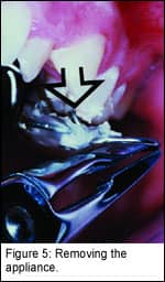
The debonding loop is the key to successful appliance removal. Weingart pliers are placed with the beaks clamped onto the loop with the base of the beaks in a fulcrum position against the bonding pad’s wire framework. With a firm movement, the plier is rotated, pulling the debonding loop facially. This makes a fulcrum of the debonding loop wire as it passes under the wire framework, and produces a vertical force on the mesial distal fossae where the debonding loop rests (Figure 5). Figure 6 represents what is generally left to clean up: some bits and pieces of material at the margins, which are easily scaled off or removed with a bur.
David Sarver, DMD, MS, has a private practice in Vestavia Hills, Ala, and is an adjunct professor of orthodontics at the University of North Carolina. He can be reached at [email protected].
References
1. Brust EW, McNamara JA. Arch dimensional changes concurrent with expansion in mixed dentition patients. In: Trotman CA, McNamara JA, Jr, eds. Orthodontic treatment: outcome and effectiveness. Ann Arbor:1995:Monograph 30, Craniofacial Growth Series, Center for Human Growth and Development, the University of Michigan.
2. McNamara JA, Brudon WL. Orthodontics and dentofacial orthopedics. Ann Arbor:Needham Press Inc;2001:211-231
3. Haas AJ. Long-term posttreatment evaluation of rapid palatal expansion. Angle Orthod. 1980;50:189-217.
4. Wertz R, Dreskin M. Midpalatal suture opening: a normative study. Am J Orthod. 1977;71:367-381.
5. Sarver DM, Johnston MW. Skeletal changes in vertical and anterior displacement of the maxilla with bonded rapid palatal expansion appliances. Am J Orthod Dentofacial Orthop. 1989;95:462-466.