by Joe Mayes, DDS, MSD
How 3D scanning can help orthodontists make their patients more attractive
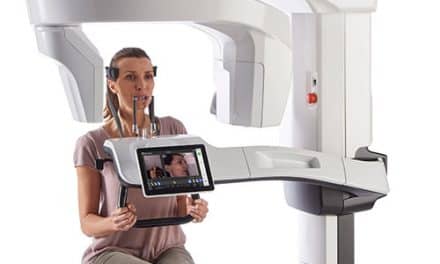
X-rays are an established and necessary part of every orthodontic practice. I believe the quotes, “You don’t know what you don’t know,” and, “You don’t know what you can’t see,” pretty much say it all. CBCT offers views of the patient in all three dimensions with none of the magnification, distortion, or superimposition found in all traditional 2D x-rays. This precision allows diagnosis and treatment plans not obtainable with traditional 2D views. This diagnostic advantage is well demonstrated in the ability to evaluate the patient’s airway competence in a 3D model accurate to thousandths of an inch. Add to that the ability to surface-fuse an accurate 3D photogrammic image, and a complete hard- and soft-tissue analysis is available, including a three-dimensional analysis of the airway.
Consider the following radiation facts.
- Just being alive exposes a patient to .008mSv of background radiation every day.
- At an altitude of 30,000 feet, traveling from Los Angeles to London, a pilot or passenger is exposed to .080mSv. This exposure explains why the pilots were concerned with going through the scanners at airports. The exposure is also equal to 10 days of normal background radiation.
- A full-mouth series of small intraoral x-rays exposes the patient to .170mSv, or the equivalent of 22 days of background radiation.
- A medical CT of the skull (obtaining the same basic information as a CBCT scan) exposes the patient to .869mSv of radiation.
- If, for example, you have your gall bladder removed, a medical CT scan of the abdomen is standard at 10.000mSv of exposure—equivalent to 3 years of background radiation.
- A routine chest x-ray exposes the patient to .080mSv and, again, is the equivalent of 10 days of background radiation.
Limiting Exposure
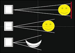
Figure 1: An illustration of 2D distortion shows that the closer the object, the more the image is distorted.
I am not pushing any products or companies, but I do have an i-CAT machine and a 3dMD photogrammic imaging machine. Therefore, these are the only machines I am familiar with, and I can’t speak about other products. How much radiation is the standard exposure with the i-CAT machine? .087mSv, the same as 11 days of background radiation exposure. Also, with the i-CAT, lower doses may be obtained based for individual patients because of diminished radiation by collimation of the needed exposure, voxel size selection, and radiation exposure based on the individual patient’s needs. The pulsed-beam technology of the i-CAT machine already offers lower radiation doses than machines that don’t use that technology.
With my machine, I can be attentive to ALARA goals by choosing the size of scan appropriate for various treatments. The system includes a full field-of-view option of 6 cm diameter and an extended field-of-view option of 17 cm x 23 cm. With collimation, I can size the scan to target a specific area of interest and change the height from 2 cm to 13 cm or anything in between. Furthermore, this collimation happens at the radiation source, reducing the exposure as the scan size lessens. Scan time also relates to resolution and exposure. The i-CAT’s 5-second scan significantly lowers the emitted dose, which is a responsible choice in the event that follow-up scans are necessary.
Although not a replacement for CBCT imaging, 3D photography represents a powerful complementary technology for evaluating patients’ facial structure and monitoring their response to the treatment plan. 3dMD’s system captures a 3D image in 1.5 milliseconds with an accuracy of 200 microns. It can be used throughout the treatment cycle and can document several facial expressions. There is no radiation with a 3dMD image.
All 2D Is Distorted
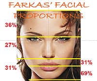
Figure 2: These are the actual proportions of an undistorted 3D image of an attractive face.
When you get into 3D information, you have to choose either 2D or 3D. 2D information cannot be evaluated by 3D guidelines, and there is no 2½ D! This is true of both hard- and soft-tissue image captures (Figure 1).
Two quotes illustrate the need for more detailed information than 2D imaging can provide, depending upon the procedure needed. According to Farkas, Tompson, Katic, and Forrest,1“… the significant differences between the measurements obtained directly from the surface of the skull and indirectly from radiographs emphasize the need for caution in patients when the latter are used to indicate morphological changes in the patients face …”
Moyers and Bookstein2 added that “… demonstrated that traditional cephalometric analysis provided limited or even misleading information regarding the true shape and size of craniofacial structures …”
Is Facial Beauty Important?
As we start a discussion of 3D imaging, the first question that comes to mind is why image at all? One of the overall goals of orthodontic treatment should be to make the face more attractive. Numerous articles have dealt with the advantage of 3D imaging for surgery cases, impactions, etc. In this article, I am only going to address 3D in orthodontic treatment from analysis to treatment planning.
I am going to explain facial beauty using the model of the Caucasian female face. In this article, I do not have the ability to evaluate all of the sex/race/age differences of various faces. Nor will I address the differences caused by growth, maturation, and aging.
So what is facial beauty? Facial beauty can be described as the positive feelings created by the physical appearance of an individual, in the absence of any other information.According to Robert B. Cialdini, author of Influence: The Psychology of Persuasion,3 “Although it is generally acknowledged that good-looking people have an advantage in social interaction, recent findings indicate that we may have sorely underestimated the size and reach of that advantage.”
Nancy Etcoff, author of Survival of The Prettiest,4 notes that, “Beauty is an advantage for men as well as women, although the magnitude is greater for women.”
What Makes a Face Attractive?
Based on reading almost 200 books and about 1,000 articles, and making multiple visits to leading authorities on facial beauty, I believe there are four main attributes that make a face attractive. I will list these in order of importance: 1) proportions; 2) symmetry;3) clear skin; and 4) a youthful look.
Let’s briefly examine the first two, as there is little we as orthodontists can do with the last two. Proportions deal with the face in a vertical orientation. In other words, comparing the proportions of the face/chin, etc. According to Victor Johnston,5 the beautiful female face has certain attributes when compared to the average face: thinner or more gracile lower jaws, a larger forehead, large eyes compared to the rest of the face, and a shorter distance from mouth to chin (Figure 2, page 18). These changes emphasize youth and male/female differences.
Symmetry deals with the face in a horizontal orientation. In other words, it compares each half of the face to the other, and they should be closely similar. However, the human eye cannot discern asymmetries of less than about 2 to 3 mm (Figure 3).
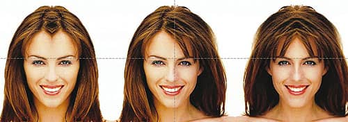
Figure 3: Elizabeth Hurley’s face shows almost perfect symmetry.
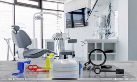
Image Capture and Surface Fusion
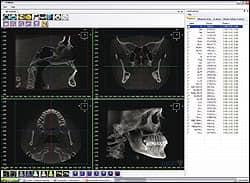
Figure 5: This view of the hard tissue is ready for point marking. The 3D image can be made to look like x-rays or actual bone.
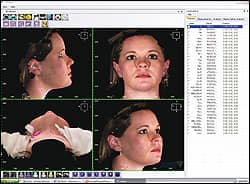
Figure 4: The 3DMd surface image and the grayscale i-CAT image are fused and ready for analysis.
Image capture takes from 4.8 to 40 seconds for the i-CAT machine, depending on the quality of image you need. Image capture with the 3dMD photogrammic imaging machine takes about 1.5 milliseconds. The two images can be fused together to create a single image for analysis. The color, rendered image is fused to the grayscale surface of the i-CAT image in a few simple steps, and the entire process, including diagnosis and treatment planning, takes less than 2 minutes (Figures 4 and 5).
Analysis and Treatment Planning
I open the fused image in 3dMD’s Vultus software. I then mark the soft-tissue points, followed by the hard tissue and airway center points. The airway may be viewed as a volume and separated from the other images. It may also be viewed as an .avi file video seen from inferior to superior. The airway may also be viewed in graphic form (Figures 6 and 7).
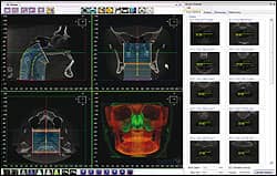
Figure 6: The airway is marked and ready to view. This can be done as an endoscopic view or as an .avi of the airway.
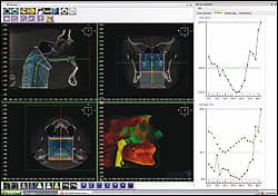
Figure 7: Another view of the airway includes the graph at right, which shows the surface area of opening.
Once the points are marked, the software creates an analysis of the soft tissue using the proportions suggested by Leslie Farkas, MD, CSc, DSc, FRCS(C). In the 1950s, Farkas introduced the idea of collecting and evaluating facial structure data as a foundation to evaluating how effectively surgeons were achieving an aesthetic outcome in comparison to a subject of similar age and background. Over the years, Farkas’ method of evaluation has extended to all aspects of intervention to the face, and Farkas’ successors around the world continue to work on improving this foundation, supported by research grants.
I was fortunate to have had the opportunity to work with Farkas for several years before his death. He guided me in forming my method of soft-tissue analysis. The hard-tissue analysis is based on proportions, lines, and angles. It will tell if a plane is rotated in relation to other planes as well as the angle of rotation.
The software generates more information than can be evaluated in a timely manner. Therefore, I developed several pyramids and triangles to help in a rapid overview of a patient’s needs. A more complete analysis is available for more difficult cases, and you can create an individual diagnostic plan using the marked points.
Once the diagnosis is complete, it tells the orthodontist what needs to be done to make the patient’s face more attractive. All treatment options to achieve the desired result are available to the orthodontist, who can then create a patient-specific treatment plan with clear treatment goals.
Conclusion
Today’s orthodontist is fortunate to have access to modified and safe versions of the 3D technologies developed for reconstructive surgeons. We know that relatively simple interventions can be a life-changing experience for adolescents and adults alike. There can be no excuse, in the 21st century, for not deploying 3D imaging to encourage detailed planning of intervention. There can be no better testimonial to a craftsman’s work than seeing the result in an undistorted, revolving 3D photograph.
Joe Mayes, DDS, MSD, is in private practice in Lubbock, Tex. He is a frequent lecturer on new and innovative orthodontic treatments. He can be reached at
References
- Farkas LG, Tompson BD, Katic MJ, Forrest CR. Differences between direct (anthropometric) and indirect (cephalometric) measurements of the skull. J Craniofac Surg. 2002;13:109-110.
- Moyers RE, Bookstein FL. The inappropriateness of conventional cephalometrics. Am J Orthod. 1979;75:599-617.
- Cialdini RB. Influence: The Psychology of Persuasion. New York: Harper Collins; 2007.
- Etcoff N. Survival of The Prettiest: The Science of Beauty. New York: Anchor; 2000.