by M. Sarah Pompa, RDA
An imaging specialist helps her orthodontist use CBCT for diagnosis
 |
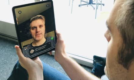
| Figure 1: A 3D image in volume mode shows an upper left impacted canine. |
Cone beam computed tomography (CBCT) has become widely known as an innovative tool used in orthodontic diagnosis and treatment-planning. The ability to produce a 3D image of the patient’s oral and maxillofacial region from one 10-second CBCT scan has sparked great interest among orthodontists worldwide.
Once a 3D image is assessed through CBCT software, any area of anatomy may be isolated and examined. Views are available to diagnose impacted canines and wisdom teeth, as well as the temporomandibular joint. Orthodontists can also capture panoramic views of dentition, soft and hard tissue assessment for cephalometric analysis, root configuration in the alveolar process, symmetry of arches … the list goes on.
3D imaging not only improves an orthodontist’s diagnosis, but is also a means of communication among colleagues. Doctors now have the ability to observe and discuss the “virtual” patient together or simply hand over a CD of different views of the patient. Doctors aren’t the only ones interested in CBCT. As more and more orthodontists integrate CBCT technology into their practices, it will be the staff members’ role to develop skills in using the 3D imaging software to help the orthodontist.
The Initial Exam Appointment
In the initial exam appointment, the orthodontist will determine whether a patient is a candidate for a CBCT scan. In the office of Ray Sugiyama, DDS, MS, where I work, about 25% of patients get a 3D scan. The reason why not all patients get a CBCT are necessity and x-ray radiation exposure. Also, cost and staff time are taken into consideration. The cost of a CBCT scan is usually higher for the patient than film x-rays. Also, with each scan I have to put the time into creating diagnosable records.
Cases that are appropriate for a 3D x-ray include surgical cases, impacted canines and wisdom teeth, temporomandibular dysfunctions, facial asymmetries due to skeletal problems, and patients with periodontal issues and/or sinus and airway obstructions. If any patient falls under one of these categories, Dr Sugiyama will fill out a CBCT scan prescription form made available by Rite-Scan, the 3D x-ray and 3D photo lab nearest to his office. On the prescription form, there are detailed drawings of a model skull in order for him to circle any specific areas of interest.
 |
| Figure 2: A buccal view of the left condyle shows flattened condylar heads, which indicate severe TMD. |
The CBCT machine used at Rite-Scan can be adjusted to scan in either a 6-, 9-, or 12-inch diameter. Considering that an orthodontist will want to see all of the landmarks used in a cephalometric analysis, Dr Sugiyama asks for the scan in the 12-inch diameter.
Dr Sugiyamacan choose to receive the data on a CD or on printed sheets of photo paper. Dr Sugiyama always requests that the raw data from each scan be sent to him on a CD, because he has invested in CBCT software in his own office. The software allows him to view the patient in 3D at any moment. Also, I create the reports according to his specific instruction, which may vary from case to case. This means that I too had to be trained on the software. So 3D imaging has not only provided advantages in diagnosis and treatment planning, but has also created a new role for orthodontic staff members.
Training in 3D
When Rite-Scan bought its 3D machine about 3 years ago, 3D imaging was so new that classes on the subject were hard to find. In order to learn about this new realm in orthodontics, I went to as many lectures and seminars on CBCT as possible. Several valuable lectures were held at the University of Southern California as well as at AAO Annual Sessions. I had the advantage of being present during the initial stages of the installation of the CBCT machine at the lab. This allowed me to receive one-on-one software training. I have also been trained at both Loma Linda University and at the University of Southern California on the subject of 3D imaging and using the imaging software. Anyone dealing with 3D imaging should keep up on the latest articles involving CBCT.
Capturing the Data
The total appointment time for each patient at the CBCT lab will typically be only about 15 minutes. The machine’s total scan time is only 10 seconds. This includes no periapicals or preparation other than removal of any jewelry and accessories. It is important that the patient remain as still as possible during the 3D x-ray, just as he or she would during a medical CT or CAT scan. After being scanned, the patient is free to go and the lab then delivers the 3D scan on a CD to our office.
Each scan is about 256 megabytes on a CD. The scan is in Digital Imaging and Communications in Medicine (DICOM) format. DICOM is a type of digital file commonly used for medical purposes. The raw data of one scan consists of 512 axial slices (a horizontal slice of anatomy that is a foot-view looking toward the top of the patient’s head). Each slice is 0.38 mm thick. Axial slices are the views that have been commonly produced by traditional CAT scans and developed on large sheets of film. With cone beam technology, axial slices are “stacked” on top of one another in the CBCT software, thus producing a 3D image of the patient’s head.
 |
| Figure 3: A 3D view shows dentition and roots. Notice the ability to cut and slice the image within the imaging software. |
Choosing Your Views
Once the CD is delivered to me, I import it into the CBCT software. This consists of putting in the CD, opening the software, and clicking “import DICOM data.” From there, it takes about 10 minutes for the data to load into the computer. After the scan has been imported into the software, the name of the patient will be added to the list of scans that have been previously imported. Once the patient’s scan has been “opened” within the software, three initial 2D views of the hard and soft tissue of the patient’s entire head are present: axial (a foot view looking up), sagittal (a side or lateral view), and coronal (a frontal view). This is called the multiplanar reconstruction (MPR) mode, since the patient’s image is available in three different planes of space. Each 2D view consists of 510 slices, each one only 0.38 mm thick (512 slices for axial view). These views are in grayscale, but color can be added to either hard or soft tissue in order to isolate or highlight areas of the anatomy. The main advantage of the three 2D views is the detail that heightens the differentiation between hard and soft tissue. Root configuration in the alveolar process is greatly apparent in both axial and sagittal views. Bone loss, periodontal issues, impacted teeth, TMJ issues, and sinus and airway obstructions are all clearly visible in the MPR mode.
2D views of the patient’s anatomy are not limited to the three angles visible in MPR mode. The “oblique” tool allows the user to place a cursor over any area of the anatomy and view it in a fourth plane, which is any angle desired. The thickness of the oblique slice can be anywhere from 0.38 mm to 40 mm. If the user chooses to expand the slice thickness anywhere past 0.38 mm, the image is then converted to a 3D section of the patient’s anatomy using the “oblique thickness” tool. This can be very valuable when viewing the patient’s TMJ in all three planes of space. You can isolate the condyles within your oblique thickness tool and are able to crop surrounding areas of tissue in order to have a clear assessment of that body part.
Within the software, there are several different 3D viewing modes. “Volume” mode allows complete control of hard- and soft-tissue density or opacity of the image. With a histogram tool, you can completely add or take away hard or soft tissue. It is possible to view only the skeleton of the patient’s head, only the soft tissue (which then resembles a 3D photo of the patient), or hard and soft tissue together. Also, different colors can be assigned to various parts of anatomy in this mode. This allows a greater distinction between hard and soft tissue, creating an advantage when viewing cases with impacted teeth.
Another valuable feature within the software is viewing the patient’s 3D image in a mode called “Ray Sum.” This tool superimposes hard and soft tissue in grayscale. Ray Sum gives images in their highest resolution, producing very precise and clear cephalometric images, for example. Ray Sum is also the feature used when creating panoramic images of dentition. Because the histogram is available for soft- and hard-tissue adjustment, the user has the capability to find the best view possible for a given area of anatomy.
 |
| Figure 4: The display of the imaging software shows that 3D and 2D views are available, as well as a histogram to manipulate color and tissue density. |
Generating Reports
As a CBCT report technician, it is my job to capture the specified areas of anatomy and to create “reports” from each patient scan. Reports are simply the product of copying and pasting different views onto a template, then either printing that template or storing it in the computer. In order to capture the best views possible to later copy and paste them, the user should be fully aware of the software’s vast capabilities. The software provides a blank template just like a blank sheet of paper. Once I find the best view possible—for panoramic view, for example—I capture that image and then paste it onto the blank template. In that template I then type the patient’s name and the date the scan was taken, and label it “panoramic view.” This template is then printed as well as stored in the computer. The blank template can also be divided into sections so that you can copy several different views to one template, which is an advantage when creating reports such as impacted canine views.
- To read more on this topic, search for in our online archives.
The orthodontist has the option of viewing the reports on the computer or having prints made of each report. Dr Sugiyama prefers that I print each report in order for him to physically show and explain his plan to the patient or patient’s parents during the consultation appointment. The best computer setup for this kind of work would involve two flat screens hooked up to one computer. Most computers allow for dual screens, enabling the user to carry the mouse from one to the other just as if it were one long computer screen. The reason for this is to have the template on one screen and the software window on the other. This makes it very easy to view both at the same time, without having to switch from window to window.
3D imaging provides a broad spectrum of views of the patient’s anatomy. CBCT technology aids in diagnosis and treatment planning, and gives orthodontists the ability to communicate with dental colleagues as they can view the patient in 3D together. 3D imaging can eliminate surprises for orthodontists and may even be important in legal matters. 3D imaging is quickly becoming the new standard of care, and will continue to create new roles for staff.
M. Sarah Pompa, RDA, has lectured on 3D imaging to the students and faculty at Cerritos College, USC, UCLA, and the University of Mexicali. She has spoken to the Hawaiian Association of Orthodontists and was on the regular program at the 2007 AAO Annual Session. She can be reached at